

Multipart Rooflight with Integrated Ventilation for Roof Extensions

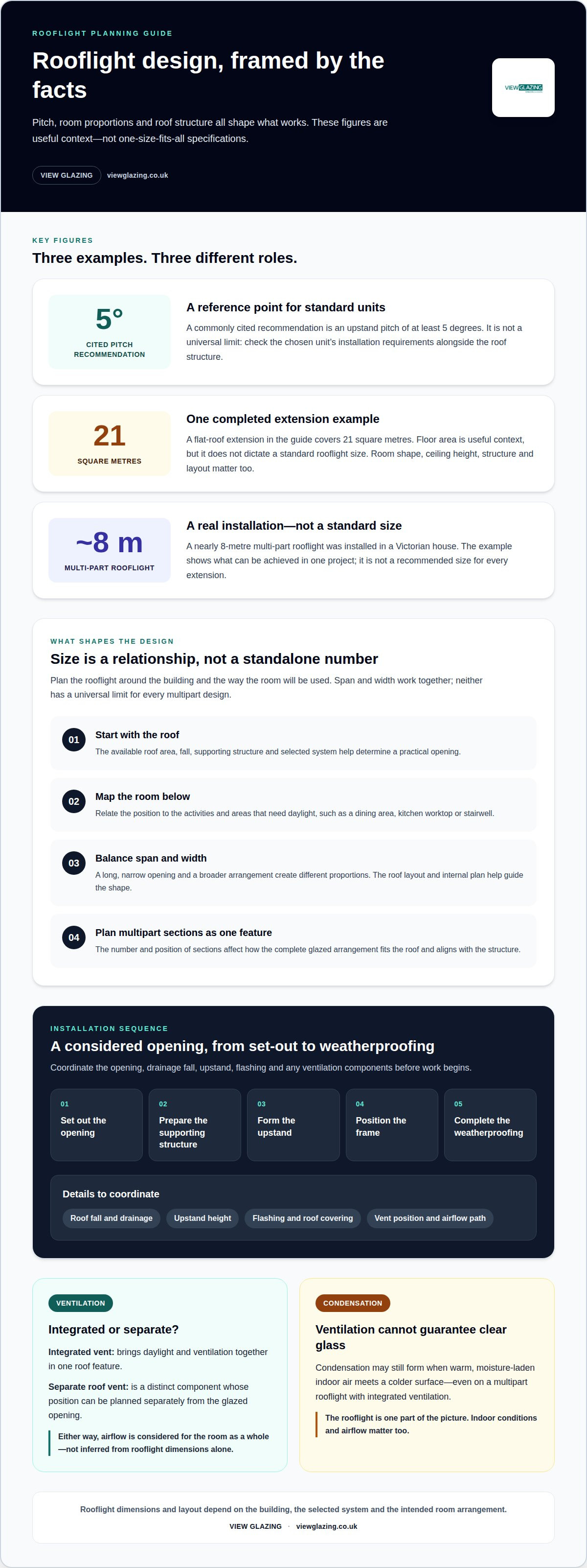
Ventilation can help manage moisture, but it cannot guarantee clear glass. Condensation may still form on a multipart rooflight with integrated ventilation when warm, moisture-laden indoor air meets a colder surface. The rooflight is only one part of the picture: indoor conditions and airflow matter too.
Choosing a rooflight for an extension means balancing the available roof area with the daylight and ventilation you want. Installation pitch, rooflight size, span and width all affect what may suit the structure and layout.
This guide explains how these factors shape your choice, what to consider when planning a larger opening, and why condensation can occur even when ventilation is integrated. You’ll have a clearer basis for discussing a rooflight design and installation that works with your extension.
Table of Contents
Installation pitch limits and recommendation
Pitch affects how water runs off the glazing and how the rooflight meets its upstand. For standard rooflight units, a commonly cited recommendation is an upstand pitch of at least 5 degrees. This is a recommendation, not a universal limit for every design. The chosen unit’s installation requirements and the roof structure must be considered together before the opening is formed.
A roof that looks flat can still have a designed fall. The installer assesses its direction, the upstand height and the roof covering around the opening. These details affect how the frame sits and how the flashing directs water away from vulnerable joints. A level, accurately formed base helps the rooflight sit as intended, without requiring adjustments during installation.
Background ventilation requirements depend on the room and the dwelling’s ventilation design, not just the rooflight pitch. An integrated vent is one part of the planned airflow, assessed alongside the room’s other ventilation provisions. The arrangement is therefore considered for the space as a whole, rather than inferred from the rooflight’s dimensions.
Planning permission and permitted development rules can affect a rooflight installation. Whether approval is needed depends on the property and proposed work, including its location and design. Consider these factors before finalising the roof opening. They are separate from the practical pitch assessment, which concerns the roof construction, unit requirements and weatherproofing details.
Installation follows a sequence: set out the opening, prepare the supporting structure, form the upstand, position the frame, then complete the weatherproofing. Flashing joins the rooflight edge to the surrounding roof covering and directs water away from the junction. Its shape and position must suit the roof material and the unit’s installation details. Integrated ventilation components must also remain clear and correctly aligned.
Moving large glazed units requires planning before lifting begins. According to UK Government, the Manual Handling Operations Regulations 1992 apply to moving rooflights, as amended by the Manual Handling Operations Regulations MHOR2002. The route, access opening, handling method and placement sequence all affect safe movement. These considerations become especially important for multipart units, where separate sections must reach the roof and align accurately.
Before work starts, the installer coordinates the roof opening, upstand, drainage fall and flashing detail. This helps prevent clashes between the glazing frame and roof finish. For a multipart rooflight with integrated ventilation, planning also accounts for the vent’s position and airflow path. The right pitch supports drainage, accurate fitting and the intended operation of the finished rooflight.
Rooflight size and extension area
Match the rooflight’s footprint to the extension’s shape, intended use and structural layout. A large glazed area can bring daylight deeper into a room, and its position affects where the light falls. For example, a rooflight centred over a dining area creates a different effect from one beside the kitchen worktop. Start by mapping the extension’s main activities and the areas that need daylight most.
Extension floor area gives useful context, but it doesn’t dictate a standard rooflight size. One completed flat-roof extension covers 21 square metres. That example shows why the opening needs to be considered in relation to the actual room, rather than chosen from the floor area alone. Ceiling height, room shape, roof structure and the position of walls all affect how glazing will feel inside.
A nearly 8-metre multi-part rooflight was installed in a Victorian house. Its length demonstrates how several sections can form one extensive glazed feature across a roof. It isn’t a recommended size for every extension. The support structure, roof opening and intended layout determine whether a similar span makes sense. Size decisions should therefore begin with the building, not a headline dimension.
Integrated ventilation combines the rooflight and an opening vent within one overall design. A separate roof vent is a distinct component, so you can plan its position separately from the glazed opening. The integrated approach brings daylight and ventilation together in one roof feature; a separate vent gives you another location to coordinate. In either case, the extension’s layout and airflow needs shape the choice.
Before settling on dimensions, plan the opening in relation to the roof structure and the room below. Mark the rooflight’s intended position on the extension plan, then relate it to internal features such as kitchen units, a dining table or a stairwell. This makes it easier to assess the glazing area against useful daylight and identify where structural supports may affect the clear opening.
For a multipart design, consider the whole glazed arrangement as well as each section. The number and position of the sections affect how the rooflight fits within the available roof area. A long, narrow opening creates a different visual proportion from a broader arrangement. The building’s geometry, roof edges and internal plan help determine which shape is coherent and practical.
Use the extension plan, roof dimensions and preferred internal layout to develop a considered size. Discuss rooflight dimensions and layout for a project where daylight and ventilation need to work together.
Rooflight span and width limits
Span is the distance a rooflight crosses; width is its measurement across. Both dimensions affect how the opening fits the roof structure and the room below. A long, narrow rooflight can follow a corridor, while a wider arrangement can bring daylight across a central living area. The right proportions depend on the roof layout, not simply the extension’s floor area.
There is no universal span or width limit for every multipart rooflight. The practical limit depends on the selected system and the design of the supporting roof. As the opening grows, the surrounding structure must be designed to carry the roof. For example, a rooflight spanning existing rafters may need a different support arrangement from one positioned between them.
Start by establishing the clear opening and identifying the roof members around it. The design team can then relate the proposed span and width to the available support points. This helps determine whether the rooflight can fit within the existing structure or whether the opening needs structural changes. A measured roof plan is more useful than choosing dimensions from an internal room sketch alone.
Multipart construction divides a larger glazed area into connected sections. The position of those divisions affects the appearance from inside and how the arrangement meets the roof structure. For example, a central division may align with a structural support, while an offset division may suit an asymmetrical extension. Consider the frame lines alongside ceiling features and sightlines.
Width also affects the rooflight’s relationship to nearby roof edges, walls and drainage routes. A broad opening close to an abutment can leave less space for the surrounding roof finish, while a narrower design may preserve a wider roof margin. These details influence how the finished opening sits within the roof, so coordinate the planned dimensions with the roof covering and internal layout.
The overall rooflight size is not the same as the unobstructed glazed area. Frame sections and structural divisions take up space within the overall dimensions. When comparing layouts, consider where those lines fall above key areas, such as a kitchen island or dining table. A dimensioned plan shows whether the divisions complement the room or interrupt a preferred view.
To settle on span and width, coordinate three elements: the roof structure, the intended room layout and the chosen multipart system. Changing one dimension can affect support positions and the visual balance of the glazing. Design a broad opening as part of the extension, rather than leaving it as a final roof detail after the structure is fixed.
What sizes, glazing options and ventilation configurations are available?
A multipart rooflight can be arranged to suit a larger roof opening, with its overall dimensions planned around the structure and room below. The glazing specification also shapes the finished unit. For one stated multipart configuration, the outer pane is 6 mm clear toughened, heat-soak-tested glass, followed by a 16 mm argon-filled cavity and a warm-edge spacer bar. The inner pane is clear, soft low-E laminated glass, specified as 8.8/ 9.5 mm.
That build-up describes a particular glazing configuration, not every rooflight. It shows how the outer and inner panes can use different glass types and thicknesses. In this specification, the outer pane is toughened glass and the inner pane is laminated. The assembly also uses a black silicone-sealed cavity. Compare the full specification, as each part contributes to the unit’s construction, rather than choosing by pane thickness alone.
Two standard safety-glass options list a 6 mm outer pane: toughened safety glass, and toughened outer glass paired with laminated inner glass. The latter has an 8.8 mm inner pane. Both stated options have a centre-pane U-value of 1.1 W/(m2.K). This figure relates to the centre of the glazing, so it should be read as a glazing specification rather than a complete assessment of the installed rooflight.
Size and configuration are linked. A multipart layout divides the total glazed area into sections, and the vent’s position must work within that arrangement. The roof plan, supporting structure and preferred internal view help determine where the sections sit. For example, an opening vent above a circulation area may make more sense than one directly over fixed kitchen units. The layout must also allow the vent to open as intended.
Integrated ventilation means the vent is incorporated into the rooflight design, rather than planned as a separate roof opening. Its position and operation depend on the chosen configuration. Ventilation supports airflow, but it does not prevent condensation in every indoor condition. Moisture levels, room use and surface temperatures still affect whether condensation forms.
Before choosing, compare the overall dimensions, glass build-up, stated U-value and vent location as one specification. Check how the glazing divisions align with the extension’s layout and where airflow is needed. This gives you a clearer basis for choosing between a fixed glazed area and a design with an opening section, without assuming that every size or glass combination is available in every configuration.
The Flushglaze Multipart Rooflight can be configured with wall abutments on a maximum of three sides. Keep this limit in mind when reviewing how the unit meets adjoining walls and fits the roof opening. Consider the abutment arrangement alongside the glazing divisions and any chosen vent position, so you can assess the configuration as a whole before finalising dimensions and installation details.
What U-values, thermal performance and energy-efficiency ratings are typical?
Thermal performance depends on the complete rooflight assembly, not glass thickness alone. A stated centre-pane U-value for two standard glazing options is 1.1 W/(m2.K). This figure describes heat transfer through the central glazing area. It isn’t the whole-unit value, which also accounts for the frame and edges. When comparing specifications, distinguish between centre-pane performance and the performance of the complete installed unit.
The glazing build-up helps explain the result. One configuration uses a 6 mm clear toughened outer pane and a 16 mm argon-filled cavity. A warm-edge spacer bar separates the panes, while the inner pane is clear, soft low-E laminated glass. These components work together as a glazing assembly. Low-E glass has a coating that reflects heat back into the interior, while the cavity separates the panes.
U-value measures heat passing through a building element. A lower value indicates less heat transfer through that element. It is useful for comparing like-for-like specifications, but a centre-pane figure is not the complete rooflight rating. The frame, roof junction and installation details also affect the finished opening’s overall thermal performance.
An insulated timber upstand is described as surpassing the requirements set out in Part L of the Building Regulations. The upstand forms the raised supporting edge around the rooflight, so its insulation matters alongside the glazing specification. This is why the assessment should include the perimeter detail, not just the glass. For example, a high-performing pane cannot compensate for a poorly considered connection to the surrounding roof.
Energy-efficiency ratings and U-values describe related but different things. A U-value measures heat transfer through a component; an energy rating may assess a broader product or building context. Do not treat a single centre-pane U-value as a complete rating for the extension. Consider the stated glazing figure, frame, insulated upstand and junction details together when reviewing thermal performance.
For a multipart rooflight, compare each specification with the extension’s design and intended use. Note whether the stated value refers to the centre pane or the complete unit, then consider how the frame and upstand connect to the roof. This gives you a clearer basis for assessing heat loss and selecting glazing, without assuming one figure represents every part of the assembly.
For help relating glazing specifications and insulated upstand details to your project, contact View Glazing.
School projects may also sit within wider design and procurement requirements. The DfE scheme described for upgrading schools using modular building solutions is valued at 3bn. For school designers, thermal performance is only one part of specification: the Department for Education's Building Design Bulletin 90 says school designers, working with local contractors and architects, must ensure compliance with Part L and help achieve higher BREEAM ratings.
Where the design uses a continuous rooflight, its structural specification is another consideration. The continuous rooflight structure is designed to withstand impact from a large soft body with energy up to 1200 J, as specified in EN 14963. This impact provision does not replace comparing glazing and whole-unit thermal values; it adds a distinct performance requirement to review alongside the project's overall design.
View Glazing
View Glazing can help you plan how the extension’s windows and doors work alongside its rooflight. Turn to the team when you’re planning the wider glazing scheme and want the rooflight, views and openings to fit the same architectural vision.
For example, choosing VELFAC Composite Windows, Rationel Timber Windows, Cortizo Aluminium Sliding Doors or Flush Composite Entrance Doors can shape the look and feel of the completed extension. Bringing these elements together during planning helps you consider their proportions, materials and relationship to the room.
For a considered approach to your extension’s glazing, contact View Glazing.
Plan the next step for your extension
A rooflight is part of a wider design conversation: how daylight, fresh air and the room’s glazing should work together. Before moving ahead, bring the roof plan and intended room layout into the discussion. These help connect the design choices with how you want the extension to feel and function.
A multipart rooflight with integrated ventilation can be considered as part of the wider glazing scheme, rather than as an isolated feature. View Glazing’s range includes VELFAC Composite Windows, Rationel Timber Windows and Cortizo Aluminium Sliding Doors, giving you options to consider across the overall project.
If you’re ready to discuss how your rooflight fits the extension, talk through your rooflight plans with View Glazing. A considered conversation can help you move towards a cohesive design with confidence.
Frequently Asked Questions
Will The Glass Get Condensation?
Yes, condensation can form when moist indoor air meets colder glass. Integrated ventilation can help move air through the room, but it cannot control every source of moisture or keep glazing warm in all conditions. Cooking, bathing and drying laundry, for example, can raise indoor humidity. Appropriate room ventilation and limiting excess moisture can help manage condensation around a rooflight.
What is a multipart rooflight with integrated ventilation?
A multipart rooflight is a glazed roof opening made of connected sections, with ventilation incorporated into the overall arrangement. The opening section allows airflow while the other sections can remain fixed. This brings daylight and ventilation into one roof feature, rather than placing a separate vent elsewhere. For an extension in Bristol or Bath, the design needs to suit the roof structure and room layout.
What are the condensation, draught, leak and maintenance risks?
Condensation can occur when indoor moisture meets cold glazing; an opening vent does not remove every cause. Draughts may result from gaps around a poorly fitted frame or vent. Leaks can develop where the rooflight, flashing and roof covering meet if those junctions are not correctly formed. Maintenance should include keeping drainage paths clear and inspecting accessible seals and moving parts for wear, so you can identify developing issues early.
Comments